BIGSHINE
Integrated Motorized Screen
Retractable motorised projector screen for meeting rooms, classrooms and home viewing.

Large tubular series / LT-INT
A motorised screen for everyday rooms.
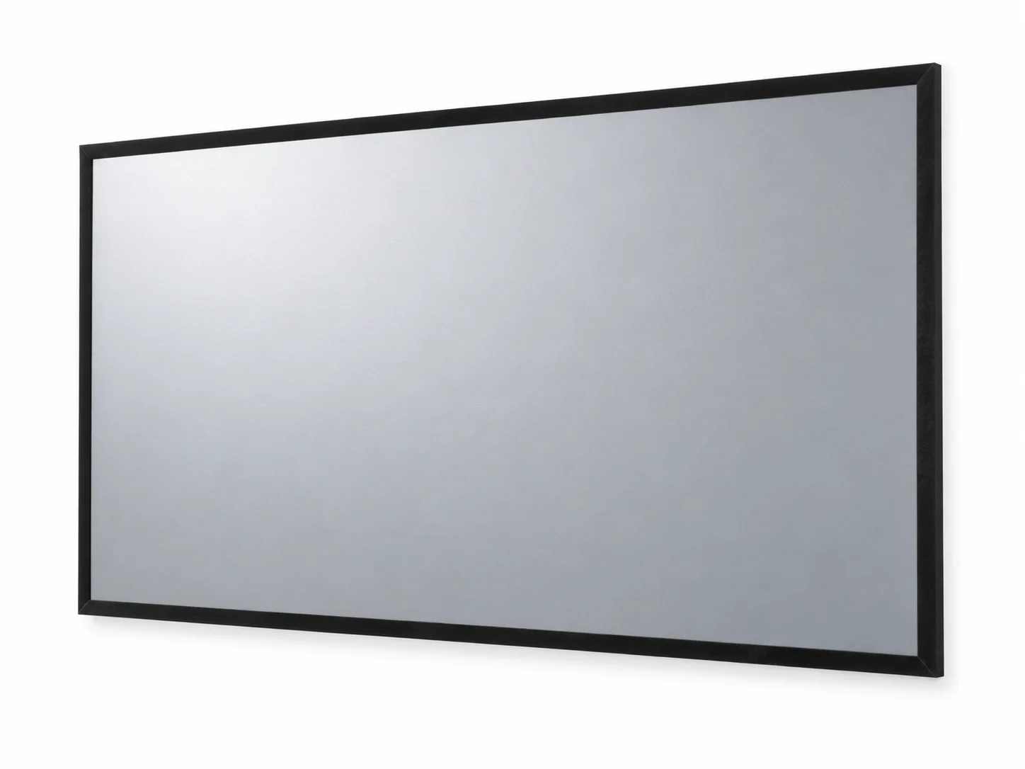
The BIGSHINE LT-INT is a retractable motorised projector screen for meeting rooms, classrooms and home viewing. Its powder-coated aluminium casing keeps the screen discreet when it is rolled away.
- Screen type
- Motorised, retractable
- Casing
- Powder-coated aluminium alloy
- Typical spaces
- Business, education and home
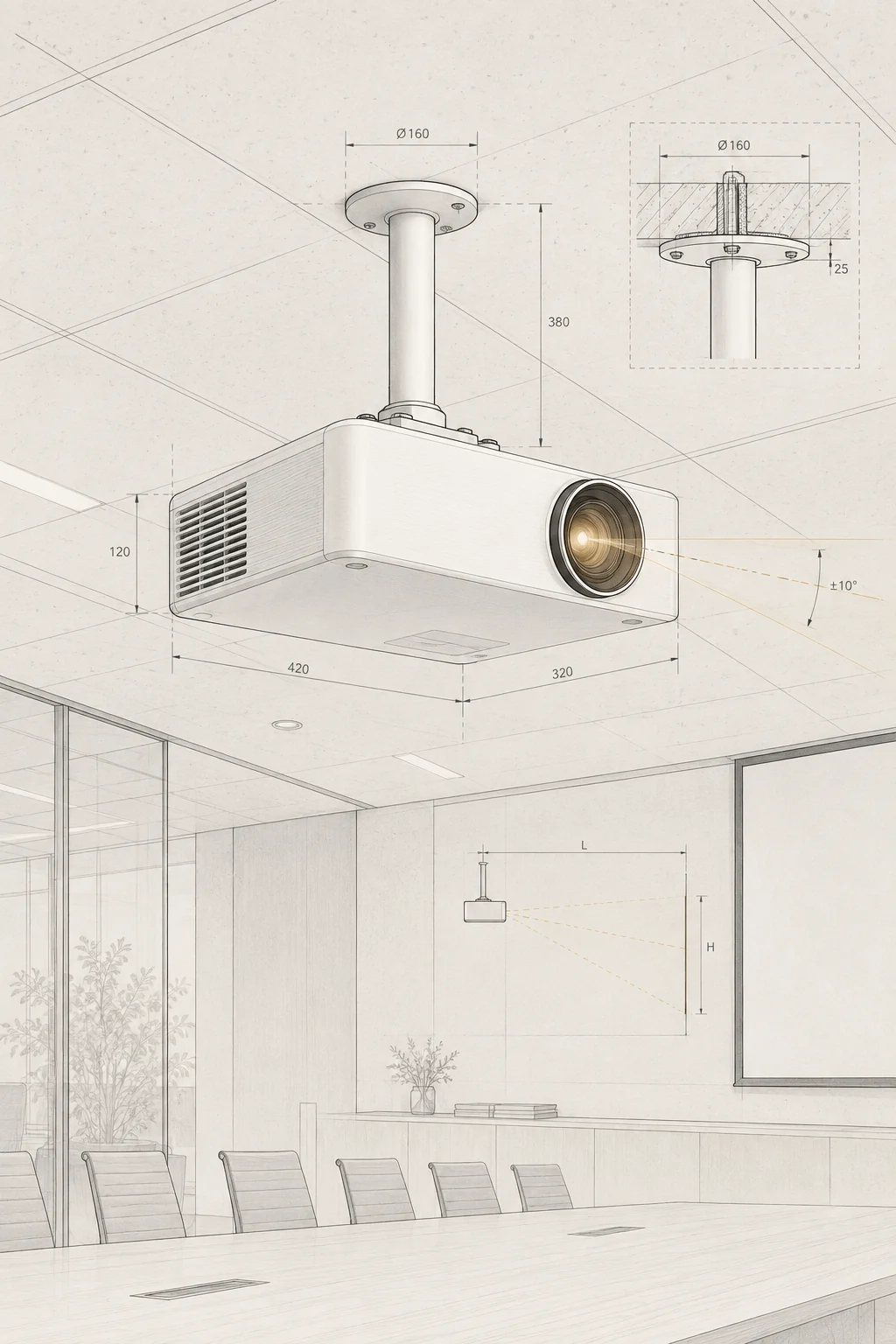
Suitable for standard and short-throw projectors. This screen is not intended for ultra-short-throw projection.
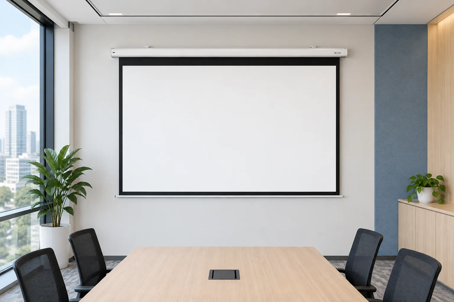
Built into the room. Rolled out for the image.
The LT-INT integrated motorised projector screen pairs an aluminium casing with matte white projection fabric, listed at 1.1 gain in the current catalog. Each surface has a different job: the housing stays discreet in the room, while the fabric presents the projected image.
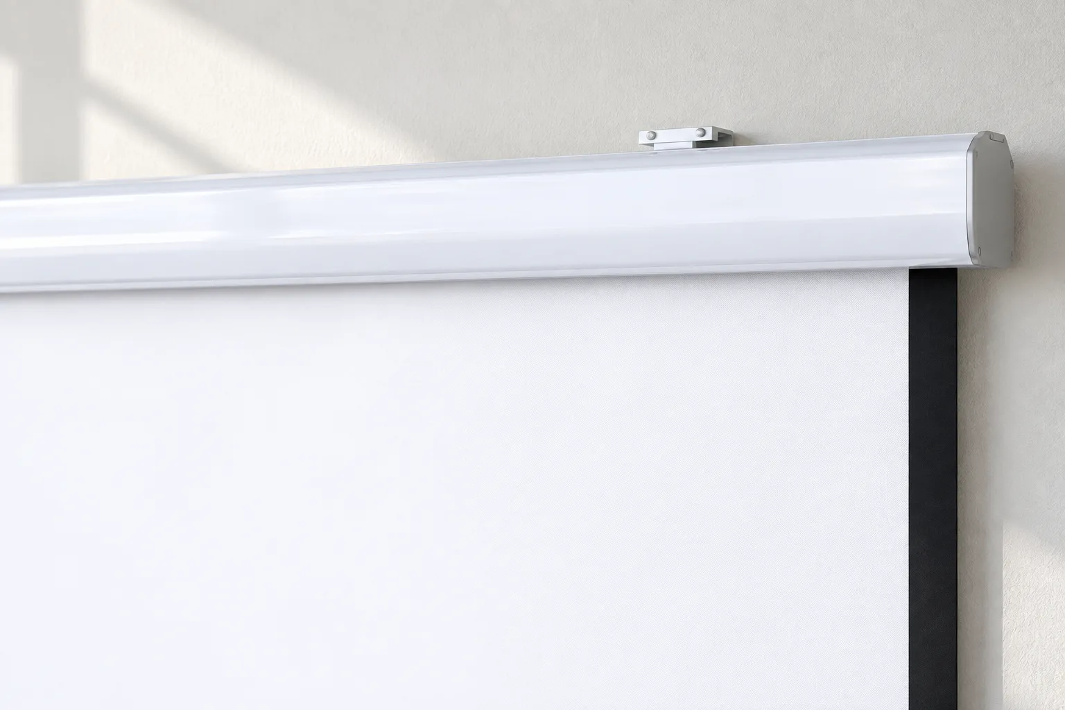
Powder-coated aluminium casing
The current catalog lists a powder-coated aluminium casing. Confirm the exact colour and finish for the supplied model when planning the installation.
Matte white projection fabric
The current catalog lists matte white fabric with a gain of 1.1. Confirm the chosen screen size and projector throw separately.
Size, casing, control and fit.
Read the letters on the drawing, find your model in the table, choose how the screen will be operated, then check the pocket, box contents and care notes before ordering.
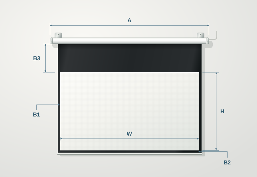
05 All 8 sizes mm unless noted
A wide viewing surface for 16:9 projection.
3 modelsA square viewing surface for 1:1 projection.
5 models| Model | Sizein | Priceex GST | W × Himage | Acasing | B1side | B2bottom | B3top | Weightkg | PocketA + 10 cm | Mounts≈ A ÷ 3 apart |
|---|---|---|---|---|---|---|---|---|---|---|
| 16:9 Widescreen | ||||||||||
| LT-INT80W | 80 | S$570 | 1,778 × 1,000 | 2,110 | 30 | 30 | 450 | 11.6 | 2,210 | ≈ 703 |
| LT-INT100W | 100 | S$670 | 2,210 × 1,245 | 2,530 | 40 | 40 | 450 | 14.0 | 2,630 | ≈ 843 |
| LT-INT120W | 120 | S$850 | 2,667 × 1,499 | 3,000 | 40 | 40 | 450 | 16.9 | 3,100 | ≈ 1,000 |
| 1:1 Square | ||||||||||
| LT-INT70 | 100 | S$535 | 1,778 × 1,778 | 2,110 | 30 | 30 | 45 | 11.6 | 2,210 | ≈ 703 |
| LT-INT84 | 120 | S$650 | 2,132 × 2,132 | 2,470 | 40 | 40 | 45 | 13.6 | 2,570 | ≈ 823 |
| LT-INT96 | 136 | S$780 | 2,436 × 2,436 | 2,755 | 40 | 40 | 45 | 15.4 | 2,855 | ≈ 918 |
| LT-INT9FT | 153 | S$1,230 | 2,743 × 2,743 | 3,065 | 40 | 40 | 45 | 17.8 | 3,165 | ≈ 1,022 |
| LT-INT10FT | 170 | S$1,440 | 3,048 × 3,048 | 3,410 | 60 | 60 | 80 | 20.2 | 3,510 | ≈ 1,137 |
06 Control the reveal.
The LT-INT can be operated as part of a room, not just as a screen on the wall. Here is how the original brochure describes the ways to lower and raise it.
Handheld remotes
The brochure shows both infrared and radio-frequency remotes for everyday operation from the room.
Legacy brochure · confirm current kitWall control
A wired wall-mounted control provides a fixed place to operate the screen.
Legacy brochure · confirm current kitProjector trigger
A 12 V trigger input can lower and raise the screen with a compatible projector’s power state.
Current catalog featureCentral control
The brochure illustrates an RJ45 central-control connection for an automated AV setup.
Legacy brochure · confirm connector
07 In the box
- 2×Mounting brackets
- 4×Bolts
- 1×Adjustment tool
- 1×12 V trigger cable
- 1×Central control cable
- 1×Wall-mount remote
- 1×RF remote
- 1×IR remote
Motor receiver
- Working temp
- −20 to +85 °C
- Power output
- < 300 W
- RF frequency
- 433.92 MHz
- Sensitivity
- −110 dBm
08 Recess and load
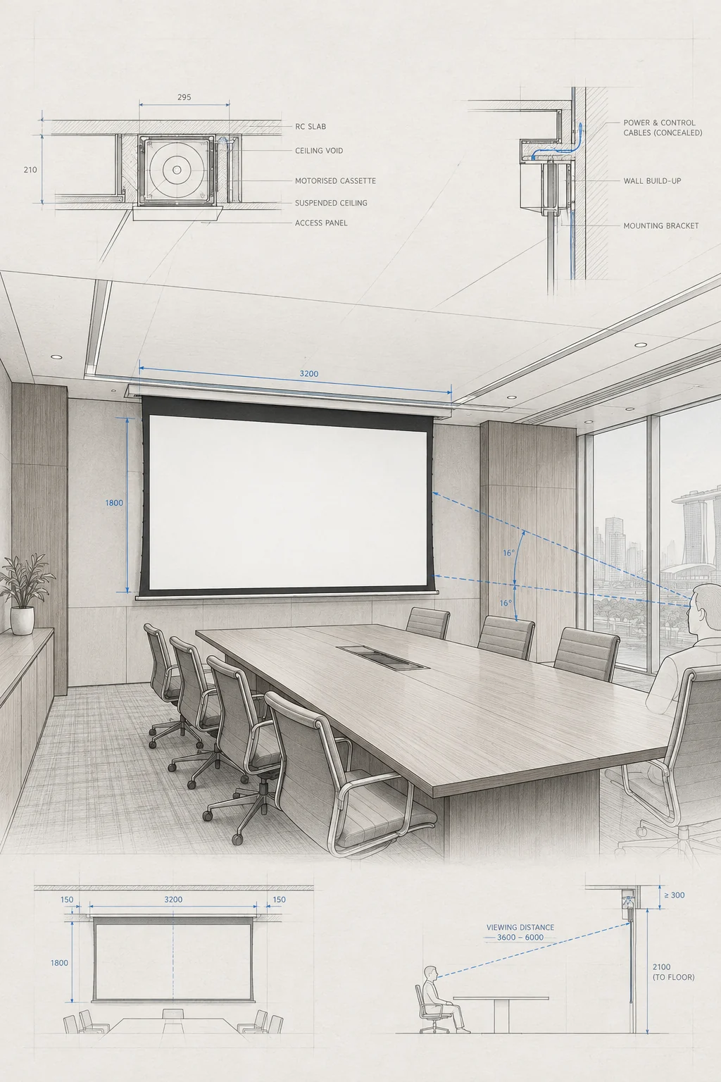
Recessed ceiling pocket, at least
- Length
- A + 100mm
- Height
- 201mm
- Depth
- 192mm
- Confirm the ceiling or wall can carry the screen’s net weight (see table).
- Mount the casing securely and level so the fabric rolls straight.
- Operate it only with the supplied controls. Do not connect other electrical attachments or remotes.
Technical manual, as built
Redrawn from the real hardware. Illustrative, not to scale.
Seen from behind, where the hook is.
Three parts
The I-beam rides in the channel on top of the casing. The L-mount’s top channel slides over the I-beam, and the hook at its foot catches the lip on the back.
On the wall
Screws go through the back leg of the L-mount into the wall.
From the ceiling
Screws go up through the top of the L-mount into the ceiling.
01Release the I-beam
Unscrew the I-beam and slide it out of the casing channel.
02Lift off the L-mount
Detach the L-mount from the casing. Repeat for the second bracket.
03Position the brackets
Align and fix the two L-mounts to the wall or ceiling.
04Hook on the casing
Hang the casing onto the back hook of each L-mount.
05Return the I-beam
Slide the I-beam to the middle of each L-mount and fasten it with the supplied tools and screws.
06Mounted in position
The casing is supported by both brackets, with the locking pieces secured.
Profiles redrawn from a video of the LT-INT hardware; proportions are approximate. Step drawings are seen from behind the screen so the hook is visible. Based on the original LT-INT brochure. Drawings explain the mounting arrangement and are not to scale. Confirm the supplied hardware, fixing method and bracket spacing with your installer.
10 Set the screen height Set to maximum height at the factory
Red knob adjusts the stopping height. Find it from below, at the bottom-left end of the casing.
White knob is not for adjustment. Turning it unnecessarily may damage the screen.
Lower slightly
Run the screen down 10–20 cm first.
Turn anti-clockwise
Turn the red knob anti-clockwise to raise where the screen stops.
Test it
Run the screen fully down with the remote to check the new height.
- Still too low?Repeat step 2.
- Too high?Turn the red knob clockwise to lower it, then test again.
11 Use and care
Everyday use
- Roll the screen back into the case after every use. It keeps dust off and stops the fabric loosening.
- Do not pull the sides, fold the fabric, hang anything on it or climb on it.
- Do not disassemble the screen. Loose parts can cause it to fall, so contact your dealer for repairs. Misuse may cause injury or damage.
Surface care
- Do not touch, write or draw on the surface, or point at it with fingers or sharp objects.
- Clean the projection surface with a soft damp cloth only. No chemical cleaners or alcohol.
- Faint horizontal lines or marks along the black borders after long storage are normal. They fade once the screen has been unrolled for a while.
- Dimensions, weights, box contents, receiver figures and three control paths are transcribed from the legacy brochure and need current-stock confirmation. The 12 V trigger is present in the current catalog snapshot. Parameters may change with product improvements.
- Casing profile measurements are indicative. Pocket sizes and mount spacing are calculated from the brochure’s 10 cm recess allowance and ⅓-length mount spacing; confirm against current hardware.
- The drawing and control paths are for planning, not installation or wiring. Confirm the supplied remotes, ports and compatibility for the exact unit before ordering or installation.
Features
- Matte white fabric, 1.1 gain
- Durable aluminum casing with powder coated finish
- 160-degree viewing angle
- Integrated motor for smooth operation
- 1-year manufacturer warranty
- 12 V trigger input for automatic screen drop/rise synchronized with projector power
See it in action
Gallery