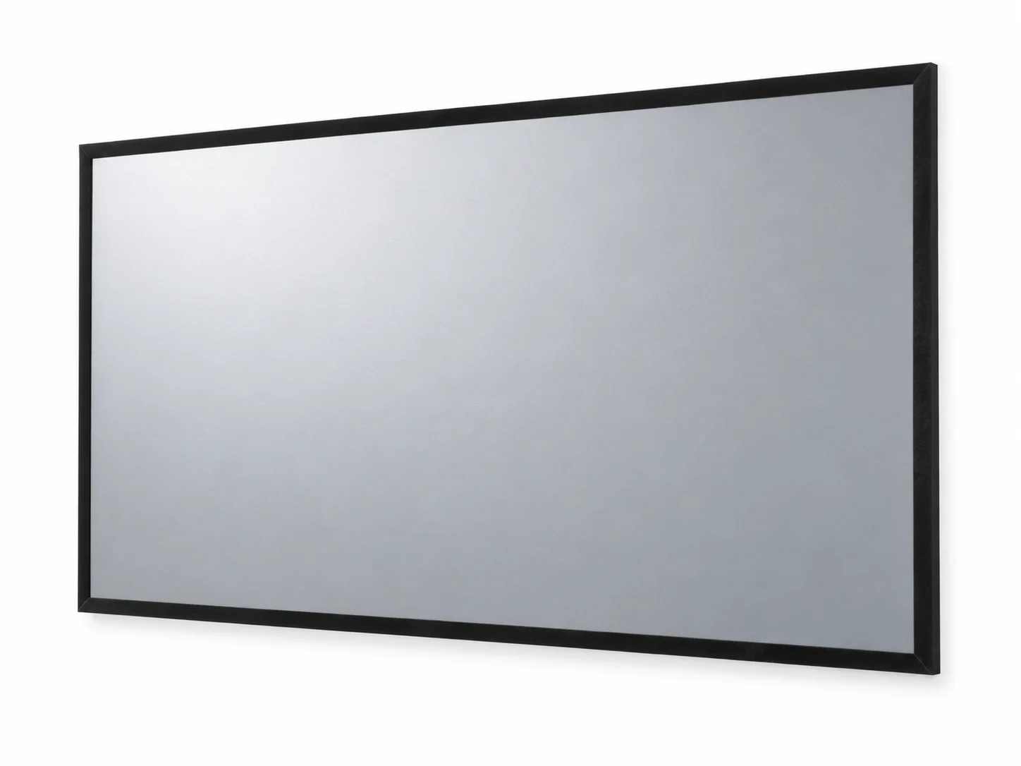
The CINE65 is a wall-mounted fixed frame screen for home cinema and dedicated projection spaces. Springs tension the silver fabric around a rigid aluminium frame, keeping the viewing surface in place between screenings.
Screen type
Fixed frame, wall mounted
Viewing surface
3D Silver Fabric / 1.5 gain
Warranty
12 months
Projector compatibility
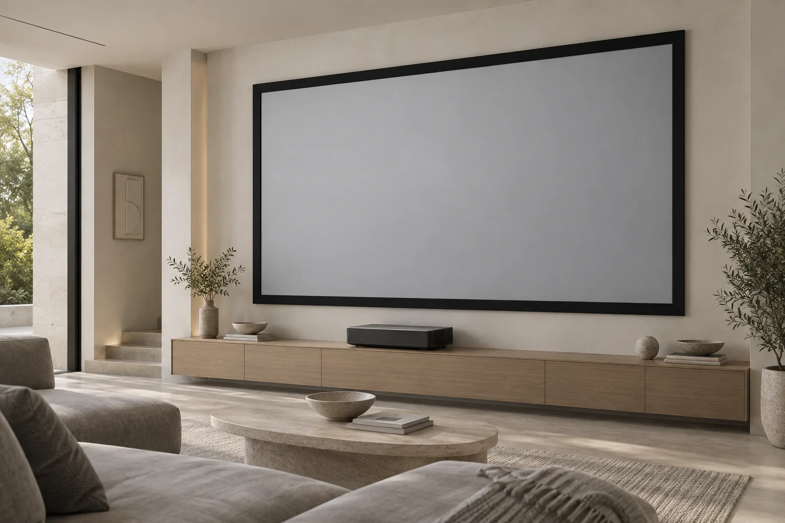
Suitable for standard, short-throw and ultra-short-throw projectors. The tensioned surface helps maintain flatness; confirm the projector position and image alignment for your room.
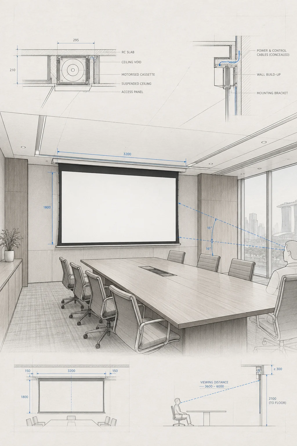
Installed-room studyIllustrative CINE65 room study; confirm projector placement and mounting.02 / Frame and fabric
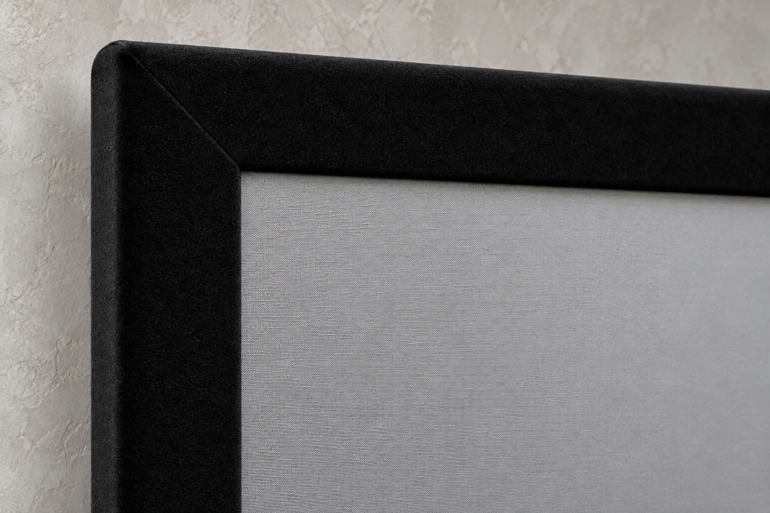
Black velvet edges. Silver at the centre.
The velvet-covered aluminium frame defines the picture edge, while the silver-grey fabric forms the projection surface. The material is listed for front projection, with a gain of 1.5 and a 60° viewing angle.
CINE65 frame and fabric study / illustrative product detail
01
The frame
Velvet-covered aluminium
Four mitred frame rails form a rigid border. The black velvet finish absorbs stray image spill around the edge. The current family specification lists a 65 mm border; confirm the 120-inch model, whose legacy brochure lists 86 mm.
02
The viewing surface
Tensioned 3D Silver Fabric
The 3DSFB-A material is listed as 3D ready and 4K UHD ready. Rods and springs attach the fabric to all four frame sides. It is not an ambient-light-rejecting or acoustically transparent fabric; plan lighting and speakers accordingly.
CN65-SMF / technical planning
A permanent screen. Planned for the wall.
Compare three widescreen sizes, allow for the frame, then plan the assembly and wall mounting. Prices follow the verified product records; dimensions and weights are legacy brochure references.
03 Dimensions100-inch front elevation / brochure dimensions. The silver area is the image; the black frame sits outside it.
05 Three sizes, one format 16:9 / mm unless noted
CINE65 models: verified Singapore-dollar retail prices ex GST; legacy brochure viewing and frame dimensions in millimetres, nominal diagonal in inches and net weight in kilograms. Confirm the 120-inch frame measurements before ordering.
Model
Sizein diagonal
Priceex GST
W × Hviewing area
Aoverall width
Fframe border
Net weightkg
CN65-SMF92W
92
S$366.06
2,032 × 1,143
2,162
65
9.2
CN65-SMF100W
100
S$411.93
2,210 × 1,243
2,340
65
10.0
CN65-SMF120W
120
S$536.70
2,667 × 1,499
2,839*
86*
16.4
Retail ex GST. Dimensions and weights follow the legacy specification sheet; the database has no model-level measurements.
*Confirm the 120-inch frame. The brochure lists a 2,839 mm overall width and an 86 mm border. The current family record lists a 65 mm border. These brochure figures remain planning references until the current-stock frame is confirmed.
06 Hardware and wall planning
Brochure kit inventory
01Four aluminium frame rails and plastic rods
02Corner brackets and corner-bracket screws
03Silver projection fabric
04Fabric-tensioning springs
05Wall-hanging brackets
06Installation hook
07Screws and wall plugs shown in the brochure
The current product guidance lists wall mounting with included brackets. Confirm the supplied kit and quantities; choose wall anchors suited to the substrate and screen load.
Room fit
Allow for the complete frame, rather than just the viewing area. The screen stays on the wall between uses.
Plan seating around the specified 60° viewing angle. Check side seats and image alignment with the chosen projector.
The silver fabric is not ALR. Control room lighting and avoid light falling directly on the screen.
The fabric is not acoustically transparent. Plan speaker positions outside the viewing surface.
Recess and mounting
The brochure asks for at least 100 mm extra in length, height and depth for a recess.
Confirm the complete frame height, frame depth, bracket envelope and access for lifting the screen onto its brackets before sizing a recess.
Use a flat wall surface, secure suitable anchors and keep the assembled frame level.
Use the supplied kit instructions for fixing positions. The illustrations do not establish bracket spacing.
07 / Installation guide
Wall mount in 12 steps
Assemble the aluminium frame, tension the fabric onto it with the supplied springs, then hang the finished screen on its wall brackets.
Surface
Assemble the frame on a clear, flat surface.
People
Two people are recommended for steps 07–08 and required for step 11.
Kit
Check the contents against the kit inventory before you begin.
Steps 01–06
Assemble the frame
01
Lay out the frame bars
Place the four frame bars on a flat surface, arranged as the finished rectangle.
Aluminium frame
02
Fit the top corner brackets
Insert a corner bracket into each end of one horizontal bar.
Corner bracket
Aluminium frame
03
Connect the vertical bars
Push both vertical bars onto the corner brackets at the ends of the top bar.
Aluminium frame
04
Check the connections
Make sure both top corners are fully connected before continuing.
Aluminium frame
05
Close the frame
Insert corner brackets into both ends of the second horizontal bar and connect it to the vertical bars.
Corner bracket
Aluminium frame
06
Screw the corners
Check every joint is well connected, then screw the frame together with the corner bracket screws.
Corner bracket screw
Steps 07–10
Fit the fabric
HandlingHandle the fabric by its edges. Do not fold it or touch the viewing surface with your hands.
2 people
07
Insert the plastic rods
Slide a plastic rod into the pocket along one edge of the fabric.
Plastic rod
Projection fabric
2 people
08
Repeat on all four sides
Fit a rod into each of the remaining fabric edges.
Plastic rod
Projection fabric
09
Hook the centre springs
Spread the fabric over the frame. Hook a spring at the centre of each of the four sides first. This makes the rest of the installation easier.
Spring
10
Attach the remaining springs
Use the installation hook to attach the rest of the springs between the fabric and the frame. Repeat on all sides.
Spring
Installation hook
Steps 11–12
Hang on the wall
2 people
11
Lift with two people
Important: two people must lift the assembled screen.
12
Hang the screen
Fix the hanging brackets to the wall with the supplied screws and wall plugs, then seat the screen onto the brackets.
Hanging bracket
Screw & wall plug
Before you let goMake sure the screen is seated securely on its brackets, so it cannot fall.
Clean with a soft, dry cloth only, following the current product guidance.
Keep hands, pens and sharp objects away from the fabric. Do not write on or fold the screen.
Do not use chemical cleaning agents or alcohol.
Keep the screen away from moisture and direct sunlight.
Keep the installation secure
Install on a flat wall and keep the frame level.
Confirm the wall, brackets and anchors can safely carry the chosen model. Brochure weights are planning references.
Use two people to lift or remove the assembled screen; protect the fabric while handling it.
Contact Big Shine if the frame, springs or mounting hardware need attention.
Before ordering
Prices, material properties and dry-cloth care follow the verified product records. Dimensions, weights and assembly follow the original CINE65 brochure.
Confirm current-stock frame measurements, especially the 120-inch model, plus the supplied brackets and installation clearances.
Room and material studies are illustrative. Assembly drawings are schematic planning guidance, not measured hardware specifications.
See it in action
Gallery
Legacy brochure and installation references. The CINE65 silver fabric is specified for front projection only; confirm the current supplied kit.